Design of Parking Sensor System Based on Ultrasonic Distance Measurement
2021-04-25
1 Introduction
In recent years, with the rapid development of the automobile industry and the continuous improvement of people's living standards, the number of automobiles in China is increasing year by year. At the same time, the proportion of non-professional motorists in motorists has also increased year by year. When reversing in crowded, narrow places such as roads, streets, parking lots, garages, etc., the driver must look ahead and take care of it, and a rear-end accident will occur if you are not careful. According to relevant survey statistics, 15% of car crashes are caused by poor rear view capability of the car when reversing. therefore. Increasing the rear view capability of the car and developing a reversing radar for detecting obstacles at the rear of the car has become a research hotspot in recent years. The premise of safely avoiding obstacles is to quickly and accurately measure the distance between the obstacle and the car. To this end, a reversing radar system with single-chip microcomputer as the core and using ultrasonic to realize contactless ranging is designed.
2 overall design and principle
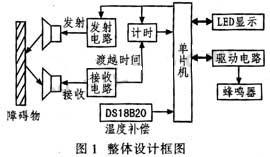
Ultrasonic generally refers to mechanical waves with a frequency above 20 kHz. It has strong penetrability, low attenuation and strong reflection ability. During operation, the ultrasonic transmitter continuously emits a series of continuous pulses that provide a short pulse to the measurement logic. Finally, the signal processed by the signal processing device processes the time difference according to the time difference, and automatically calculates the distance between the vehicle and the obstacle. The principle of ultrasonic ranging is simple, the cost is low, and the production is convenient. However, the transmission speed is greatly affected by the weather and cannot be accurately measured. In addition, the ultrasonic energy is proportional to the square of the distance, so the farther the distance is, the lower the sensitivity is. The ultrasonic ranging method is only suitable for short distances. At present, the general ultrasonic range finder at home and abroad has an ideal measuring distance of 4 to 5 m, so it is mostly used in close range ranging such as car reversing radar. The reversing radar system is controlled by a single chip microcomputer, as shown in Figure 1. Ultrasonic is used to achieve non-contact ranging, and the influence of the ambient temperature on the ultrasonic wave velocity is considered, and the velocity is corrected by the temperature compensation method. Using the temperature measurement circuit composed of the integrated digital sensor DS18B20, the temperature value can be directly read, and then the wave speed of the ultrasonic wave at a certain temperature is obtained according to the temperature compensation, and the propagation time is obtained by counting the number of pulses by the single-chip microcomputer, according to the principle of ultrasonic ranging The distance is displayed and the buzzer sound frequency is controlled according to the displayed distance.
This article refers to the address: http://
2.1 Ultrasonic Ranging Principle
At present, the methods of ultrasonic ranging include phase detection method, acoustic amplitude detection method and transit time detection method. The accuracy of phase detection is high, but the detection range is limited; the amplitude detection of sound waves is susceptible to reflected waves; the mode of operation of transit time detection is simple and intuitive, and it is easy to implement in hardware control and software design. The principle is to detect ultrasonic waves emitted from the transmitting sensor. The time difference between the receiving sensor receiving the ultrasonic wave after propagation through the gaseous medium, that is, the transit time t. The distance s=ct/2 (c is the speed of sound), t can be realized by the method of counting the number of pulses by the single chip microcomputer.
2.2 Relationship between temperature and speed of sound
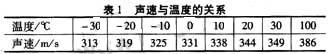
Since ultrasonic is also a kind of sound wave, its sound velocity v is related to temperature T. Table 1 lists the sound velocities at several different temperatures. When used, if the temperature does not change much, the visible sound speed is basically unchanged; if the distance measurement accuracy is very high, it should be corrected by the temperature compensation method.
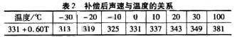
In general, temperature compensation is performed using v=331+0.60T to adapt to the working requirements at different temperatures. Table 2 shows the relationship between the speed of sound and the temperature after compensation. It can be seen that the sound velocity values are completely consistent below 0 °C; the maximum error above 0 °C does not exceed 5%.
It can be seen from the above analysis that the accuracy of the temperature measurement not only directly affects the measurement accuracy of the velocity, but also indirectly affects the measurement accuracy of the distance, so the measurement of the temperature is critical.
3 hardware circuit design
The reversing radar system is mainly composed of an ultrasonic transmitting circuit, an ultrasonic receiving circuit, a temperature measuring circuit and a display alarm circuit.
3.1 ultrasonic transmitting circuit
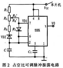
Under the control of the single chip microcomputer, the pulse generator outputs ultrasonic waves. The pulse generator consists of 555, the connection of which is shown in Figure 2. The 7-pin and 6- and 2-pin pins are R and C; the middle R is connected in parallel with the RP, RA=Rl+RA'''''''', RA=R2+RB'''''''', And T1=0.693RAC, T2=0.693RBC, the duty cycle of the output waveform can be adjusted by adjusting the resistance values of RA and RB. However, a square wave with a 50% duty cycle is required here, so adjust the sliding varistor so that T1 = T2, and the frequency is calculated as:
f=1.443/(RA+RB)C (1)
A reasonable choice of R, C allows the ultrasonic to obtain an output pulse of 40 kHz. Because the transmission of ultrasonic waves is a certain distance, in order to make the signal easy to transmit, a modulation circuit is usually added behind the transmitting circuit.
3.2 Ultrasonic receiving circuit
Because ultrasonic measuring distance is only used for close range, when the distance is far away, the attenuation is more serious, and the reflected signal is relatively weak. Therefore, the receiving end should first set up an amplifying circuit and then pass the detecting circuit. The output signal is demodulated, and finally the detection output signal is compared and shaped.
The needs of the ultrasonic receiving circuit need to consider the following aspects:
(1) Environmental noise, interference, temperature, etc.
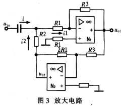
Figure 3 shows an enlarged circuit diagram. It selects a bootstrap combination circuit that increases the input impedance by reducing the current drawn to the input loop. The value is Rin=R1R2/(R1-R2), which determines R1 and R2 based on the preamble circuit. It matches the pre-sequence circuit level. The reverse-phase proportional amplifier circuit is used in the circuit, and the gain is relatively stable. Generally, K=-R3/R1 does not cause self-excitation, which can reduce the influence of interference on the circuit. Therefore, reasonable selection of R3 and R1 can make the output voltage reach the V level.
(2) Detection accuracy
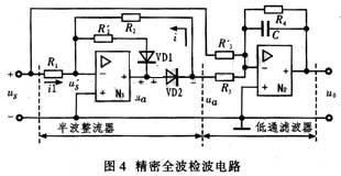
The full-wave precision detection circuit shown in Fig. 4 is used in the design. In order to improve the signal-to-noise ratio of the circuit, the unwanted frequency signal is attenuated, and a resonant circuit is added to the input end. Diodes VD1 and VD2 select IN60 with better high frequency performance. This method of detection can greatly improve the dead-band voltage and nonlinearity of the diode.
(3) Comparison shaping circuit
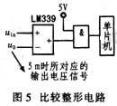
Fig. 5 shows a comparison shaping circuit. First, the distance measured by static is equal to 5 m, the output voltage of the detector (this voltage is also obtained by the amplification detection circuit), and the voltage value is used as the reference voltage uR of the comparator. The comparator uses LM339, which has small offset voltage and wide supply voltage range. Its single supply voltage is 2~36 V, dual supply voltage is ±1~±18 V, and the internal resistance of the comparison signal source is wide. For the LM339, when the voltage difference between the two inputs is greater than 10 mV, it can ensure that its output is reliably switched from one state to another. Therefore, it is desirable to use the LM339 for weak signal detection and the like. In general, the rising and falling edges of the output waveform of the comparison circuit have a delay, and an AND gate can be added after it to improve the output characteristics. The output of the comparative plastic electrophoresis is sent to the single-chip microcomputer, and the pulse is counted to obtain the transit time. The single chip selects AT89C52.
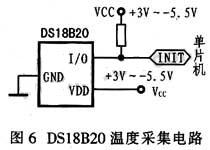
3.3 Temperature Measurement Circuits
At present, most temperature measurement and control systems use temperature sensors to convert temperature into electricity when the temperature is detected. The signal amplification circuit is amplified to the appropriate range and then converted to digital by the A/D converter. To be done. This kind of circuit is complicated in structure, complicated in debugging, and the accuracy is easily affected by component parameters. To this end, a linear digital thermometer, the integrated temperature sensor DS18B20 and a single-chip microcomputer, is used to form a high-precision digital temperature detection system. Unlike the traditional thermistor temperature sensor, the DS18B20 digital temperature sensor can directly read out the measured temperature value, and can realize 9/12-bit A/D conversion by simple programming according to actual requirements. Therefore, using the DS18B20 makes the system structure simpler and more reliable. The temperature measurement range is from -55 to +125 °C, the detection error is not more than 0.5 °C at -10 to +85 °C, and the measurement accuracy is ±2 °C over the entire temperature measurement range. The circuit connection is shown in Fig. 6.
3.4 Display and Alarm Circuit
The display circuit uses a 4-digit common-yang LED digital tube, and the code segment is driven by the 74LS244 drive circuit; the drive circuit is driven by the PNP transistor 8550. Figure 7 shows the alarm circuit. It is driven by a transistor.

4 Conclusion
The reversing radar system realizes non-contact ranging using ultrasonic waves; the temperature measurement and compensation of the ultrasonic ranging system is realized by using a high-precision temperature sensor, that is, the sound speed is compensated according to v=331+0.60T, and the measurement accuracy is improved. . The utility model has the advantages of simple circuit design, low price and high measurement precision, and has been mass-produced at present.
Laser range sensors combine the advantages of a visible red sensing beam with the increased range of a laser. The optical distance sensor devices are Class 2 lasers, support Class 1 customized. The high precision autonics distance sensor is successfully be used to connect to Arduino, Raspberry Pi, with +-1mm to 3mm high accuray, and long-range solutions (max up to 150m) for your application.
Precision Distance Sensor, Precision Laser Distance Sensor, Precision Distance Sensor Laser, Accurate Laser Distance Sensor
Stainless Steel Door Lock Co., Ltd. http://www.rangesensors.com